SiC for Generator De-Excitation
HVR silicon carbide varistors have provided a reliable solution for De-excitation systems.
An exciter in a synchronous generator is used to provide the DC supply to the electromagnetic field winding which is mounted on the rotor of the generator. In order to prevent damage being sustained to excitation systems during shut down, a suitable discharge unit for the stored energy in the coil must be available.
HVR silicon carbide varistors have provided a reliable solution for De-excitation systems.
Depending on the discharge system configuration, HVR units may be switched or permanently connected coil:
- For discharge currents less than 600A and suitable field and discharge voltages, it is possible to supply a HVR varistor which can be connected directly across the coil continuously. In these configurations, the HVR varistor have to possess a high degree of non-linearity to prevent damage at operating voltages, whilst being able to clamp transients to a protection level.
- For large coil systems, it is common to switch in the HVR varistor at the same time as switching out the supply voltage. This may be achieved via a thyristor crowbar or a field breaker. In these applications, the HVR varistor is not connected across the coil under normal operating conditions and as such considerations towards continuous power dissipation in the discs does not have to be made.For these types of applications, discs may be selected with higher current ratings and lower exponent and a lower degree of non-linearity.
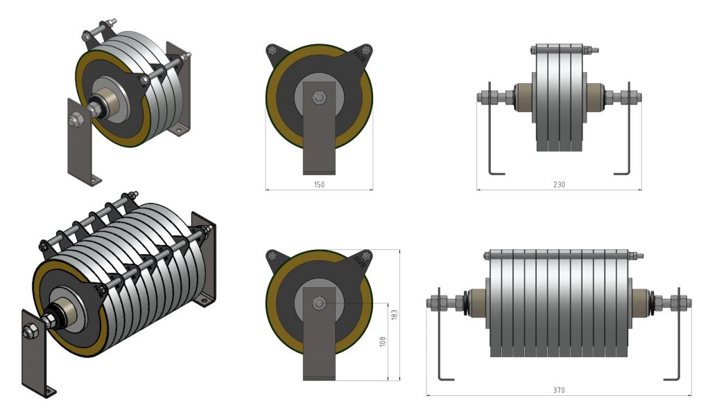
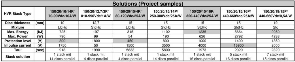
Both types are supplied as stacks of 150mm diameter discs, electrically connected in parallel. The number of discs and their thickness depends on the application details.
In the design of a HVR unit for an De-excitation system, the following parameters are necessary:
- Required protection voltage
- Maximum discharge current
- Energy stored in the field
The required protection voltage is the voltage which the HVR discs limit the system to when the maximum discharge current flows from the coil into the HVR unit.
The maximum current occurs as soon as the discharge resistor is switched in. Under normal discharge conditions, the magnitude of this current is equal to the magnetizing current used in the excitation of the field winding.
The discharge energy is the energy stored in the coil which is to be dissipated in the HVR unit.
Key features
- High performance
- Extended temperature range up to 200°C
- Higher energy rating than comparable SiC ceramics
- Higher continuous power rating
- Modular system
- Large variations of different mounting arrangements
- Highest flexibility
- Dimensions and electrical values can be modified to customer requirements
- Design service
- Design service including technical drawing to international standards
Applications
- Generators in power supply units such as hydro-electric power plants
- Very large Coils
- Big capacitor banks
Standard range
Dimensions